Architectural drawing demands exceptional precision and understanding of perspective. The grid method provides a systematic approach to accurately capturing complex building structures, from ornate historical facades to contemporary geometric forms.
Using Grids to Draw Architecture Accurately
Architecture is hard for beginners for one simple reason: small errors compound. If your verticals drift, your perspective angles drift, or your window spacing drifts, the building quickly looks “wrong” even if you draw nice lines.
The grid method fixes this by giving you checkpoints: where corners land, where edges cross grid lines, and how repeated units stay aligned.
If you want to generate a printable grid over your reference, use our grid maker online. If you want a deeper perspective walkthrough, see understanding perspective with grid drawing.
Quickstart (Beginner Workflow)
- Pick a friendly reference: clear horizon, minimal wide‑angle distortion.
- Add a simple grid: 8×10 or 10×12 is a good starting point.
- Block big shapes first: silhouette + main planes + major horizontal breaks (floors/roof).
- Place anchors: corners of doors/windows and key crossings.
- Build repetition: place first + last window in a row, subdivide in between.
- Shade in 3 values (optional): light plane / shadow plane / deep holes (windows).
Understanding Architectural Drawing Fundamentals
Architectural drawing requires a unique combination of technical precision and artistic observation. Buildings present complex challenges: multiple perspective points, intricate details, repetitive elements, and the need for structural accuracy. The grid method addresses these challenges by providing a mathematical framework for translating three-dimensional structures onto two-dimensional surfaces. For a comprehensive foundation in perspective principles, see our guide on understanding perspective with grid drawing.
The systematic nature of the grid method aligns perfectly with architectural subjects. Buildings follow geometric principles, making them ideal candidates for grid-based analysis. This technique enables artists to maintain proper proportions while managing the complexity of architectural details.
The Historical Foundation of Architectural Drawing
The tradition of using grids in architectural representation dates back centuries. Renaissance masters employed grid systems to achieve perfect perspective in their architectural studies. Architects have long used modular grids to design buildings, making the grid method a natural bridge between architectural design and artistic representation.
Modern architectural drawing continues this tradition, though tools have evolved. The fundamental principle remains unchanged: breaking down complex structures into manageable units allows for accurate reproduction regardless of scale. This systematic approach proves invaluable whether sketching a neighborhood church or rendering a metropolitan skyline.
Why Grids Excel for Architectural Subjects
Architecture inherently contains grid-like properties. Windows align in regular patterns, structural elements repeat at consistent intervals, and proportional relationships govern the overall design. The grid method capitalizes on these inherent characteristics, making it particularly effective for architectural subjects.
The benefits extend beyond mere accuracy. Grid-based drawing teaches artists to see relationships between architectural elements—how the width of a column relates to its height, how window spacing creates rhythm across a facade, or how decorative elements follow underlying geometric patterns. This analytical approach deepens understanding of architectural principles while improving drawing skills.
Modern glass office buildings reveal unexpected complexities when studied carefully. What initially appears as monotonous repetition actually contains subtle variations—reflections create different tones in each window panel, and structural elements cast intricate shadow patterns. The grid method maps these tonal shifts systematically, transforming seemingly simple subjects into sophisticated studies of light, pattern, and architectural rhythm.
Essential Tools for Architectural Grid Drawing
Success in architectural grid drawing begins with proper tool selection. The precision demanded by architectural subjects requires equipment that supports accuracy while allowing artistic expression. Understanding which tools serve specific purposes helps artists work efficiently and achieve professional results.
Traditional Drawing Tools
Pencils and Graphite
Technical pencils prove invaluable for architectural work. The consistent line weights of 0.3mm, 0.5mm, and 0.7mm mechanical pencils eliminate the variable of changing pencil points. For initial grid construction, harder leads (2H or H) create light lines that won't interfere with the final drawing. As the architectural drawing develops, artists can transition to softer leads (HB, B, 2B) for darker lines and shading.
Traditional wooden pencils still have their place, particularly for tonal work and atmospheric effects. A range from 4H to 6B provides flexibility for different architectural textures—from smooth glass surfaces to rough stone walls. The key lies in maintaining sharp points for precise line work, making a quality sharpener essential.
Paper Selection
Architectural drawings demand paper that can withstand extensive erasing and reworking. Smooth finish papers (hot-pressed) work best for detailed line work, while papers with slight tooth (cold-pressed) better suit drawings incorporating extensive shading or texture work.
Weight matters significantly. Papers of 140lb (300gsm) or heavier resist buckling and allow for corrections without surface damage. For practicing grid techniques, lighter weight papers suffice, but finished architectural drawings benefit from heavier, archival-quality papers that ensure longevity.
Precision Tools
The T-square remains fundamental for architectural drawing, ensuring perfectly horizontal lines across the drawing surface. Combined with set squares (45° and 30°/60°), artists can quickly construct accurate grids and check architectural angles. An architectural scale ruler allows for precise measurements when scaling from references, particularly valuable when working from architectural plans or photographs with known dimensions.
Quality erasers prove crucial for architectural work. Kneaded erasers lift graphite without damaging paper surfaces, while precision eraser pencils allow for detailed corrections in tight spaces. White vinyl erasers effectively remove construction lines once the drawing develops.
Digital Tools and Technology
Modern technology offers powerful alternatives and supplements to traditional methods. Digital tools can streamline the grid creation process while maintaining the artistic quality of hand-drawn work.
Grid overlay applications specifically designed for artists eliminate the manual grid construction phase. These tools allow precise grid customization, from simple uniform grids to complex perspective grids that match specific viewpoints. The ability to adjust grid density for different areas of an architectural subject proves particularly valuable when dealing with varying levels of detail.
Photo editing software with grid features enables artists to analyze reference photographs systematically. Beyond basic grid overlays, these programs often include perspective correction tools that help understand how architectural elements relate in three-dimensional space. This analysis phase proves invaluable before beginning the actual drawing.
Digital drawing tablets combine the precision of digital tools with the natural feel of traditional drawing. Pressure-sensitive styluses replicate pencil techniques while offering advantages like unlimited undo functions and layer-based workflows. For architectural subjects, the ability to work on separate layers for construction lines, main drawing, and details streamlines the process significantly.
Setting Up Your Architectural Drawing Workspace
The physical environment significantly impacts drawing accuracy and comfort during extended architectural drawing sessions. A properly organized workspace prevents fatigue and maintains the precision necessary for architectural subjects.
Drawing Surface Configuration
A stable drawing board positioned at a comfortable angle (typically 15-30 degrees) reduces neck strain and provides better sight lines to the work. The board should be large enough to accommodate both the drawing and reference materials without crowding. Many artists prefer boards that can adjust from flat to near-vertical positions, allowing flexibility for different drawing phases.
The drawing surface itself requires attention. A backing sheet of heavy cardstock or illustration board beneath the drawing paper provides consistent support and prevents indentations from affecting subsequent sheets. Some artists tape down a permanent grid sheet beneath translucent drawing paper, providing a reusable grid reference.
Lighting Considerations
Consistent, even lighting proves crucial for architectural drawing. Natural north light provides ideal conditions, but adjustable daylight-balanced artificial lighting offers more control. The light source should illuminate the drawing surface evenly without creating shadows from the drawing hand or tools.
For detailed architectural work, a combination of ambient and task lighting works best. An adjustable desk lamp allows focused illumination on specific areas while maintaining overall visibility. Avoiding glare on the drawing surface prevents eye strain during extended drawing sessions.
Reference Material Organization
Architectural drawings often require multiple reference sources—photographs from different angles, detail shots, and possibly architectural plans. A reference board or stand positioned at eye level prevents constant head movement between drawing and reference. Digital displays offer advantages here, allowing zoom capabilities and multiple reference views.
Organizing reference materials systematically saves time and maintains focus. Whether using printed references or digital displays, having a clear system for accessing different views and details prevents interruption of the drawing flow. Many artists create reference sheets with gridded versions alongside original images for quick comparison.
Grid Construction for Architectural Subjects
The foundation of accurate architectural drawing lies in thoughtful grid construction. Unlike organic subjects where grids simply aid proportion, architectural grids must account for perspective, structural alignment, and the geometric nature of buildings. Understanding how to construct and apply grids specifically for architecture elevates drawings from approximate sketches to precise representations.
Determining Optimal Grid Density
Grid density directly impacts both accuracy and workflow efficiency. Too few grid squares result in approximations that miss crucial architectural details. Excessive grid divisions create unnecessary complexity that slows progress without meaningful accuracy gains. The architectural subject itself should guide density decisions.
Simple Modern Structures
Contemporary minimalist architecture often features clean lines and large, unadorned surfaces. An 8x10 or 10x12 grid typically suffices for these subjects. The limited ornamental details and geometric simplicity mean that major proportions matter more than fine details. Modern office buildings, contemporary homes, and industrial architecture fall into this category.
When drawing simple structures, the grid primarily ensures accurate overall proportions and proper perspective. The large grid squares work well for blocking in major forms—the overall building mass, window patterns, and primary structural elements. This approach allows artists to focus on the building's essential character without getting lost in unnecessary subdivision.
Traditional and Detailed Buildings
Buildings with moderate architectural detail require increased grid density. Traditional homes with decorative trim, small commercial buildings with storefronts, and institutional buildings typically benefit from 12x16 or 14x18 grids. This density provides enough reference points for architectural details while remaining manageable.
The increased grid density allows accurate placement of elements like window trim, cornices, and entrance details. Each grid square corresponds to a smaller area of the building, providing more precise reference points for proportional relationships. This level proves ideal for most architectural drawing projects, balancing accuracy with practical completion times.
Highly Ornate Architecture
Historical buildings with extensive ornamentation demand the finest grid divisions. Gothic cathedrals, Baroque palaces, Victorian mansions, and other heavily detailed architecture may require 16x20, 20x25, or even finer grids. The intricate carved details, complex window tracery, and decorative elements necessitate numerous reference points.
Working with dense grids requires patience and systematic approaches. Artists often work in sections, focusing on one area before moving to adjacent regions. The fine grid ensures that even small decorative elements maintain proper proportion and alignment with the overall structure. This meticulous approach proves essential for capturing the full character of ornate architecture.
Gothic cathedral windows present formidable challenges with their intricate tracery patterns. The breakthrough came through isolating each tracery section within small grid squares. This systematic subdivision made the complex manageable—what initially seemed like chaotic stone patterns revealed themselves as logical geometric progressions. Those same windows that once caused frustration now serve as exercises in patient observation and methodical drawing. For foundational grid techniques that support such detailed work, see our complete grid drawing guide.
Strategic Grid Placement Techniques
Beyond density, grid positioning significantly impacts drawing success. Strategic placement can simplify complex architectural challenges and enhance accuracy where it matters most.
Aligning with Architectural Elements
Whenever possible, align grid lines with major architectural features. Placing a grid line along the building's central axis immediately establishes symmetry references. Similarly, aligning horizontal grid lines with floor divisions or major horizontal elements like cornices provides natural breaking points for the drawing process.
This alignment strategy works particularly well with classical architecture, where mathematical proportions often govern design. By matching grid lines to these inherent divisions, artists work with the building's logic rather than against it. The grid becomes less arbitrary and more integral to understanding the architectural design.
Perspective Considerations
Architectural drawings frequently involve perspective, requiring adapted grid approaches. For buildings viewed at an angle, the grid must account for convergence toward vanishing points. While the grid on the reference remains square, artists must understand how these squares translate to the perspective view in their drawing.
One effective technique involves creating a perspective grid on the drawing surface that corresponds to the square grid on the reference. This preliminary step requires extra time but dramatically improves accuracy for buildings shown in pronounced perspective. The investment pays dividends when complex architectural elements align properly within the perspective framework.
Corner buildings in two-point perspective demand careful planning and precise execution. The key breakthrough involves plotting vanishing points first, then constructing the grid to follow those perspective lines rather than forcing a square grid onto an angled view. This reversal—perspective first, grid second—transforms the approach to complex architectural angles. Understanding these perspective principles becomes clearer with our guide on understanding perspective with grid drawing.
Focal Point Emphasis
Not all areas of an architectural drawing require equal detail. Strategic grid placement can emphasize focal points while simplifying less important areas. For instance, when drawing a building with an elaborate entrance, artists might use a denser grid around the doorway while maintaining a simpler grid for plain wall surfaces.
This selective approach maximizes efficiency without sacrificing accuracy where it counts. The detailed grid ensures the focal point receives proper attention, while simpler areas progress quickly with basic grid guidance. This strategy proves particularly effective for large architectural compositions where uniform detail would be impractical.
Advanced Grid Construction Methods
Beyond basic square grids, architectural subjects sometimes benefit from specialized grid systems that better match their unique characteristics.
Modular Grids for Repetitive Elements
Many buildings feature repetitive modular elements—identical windows, regular column spacing, or standardized panel systems. Creating a grid that aligns with these modules streamlines the drawing process. Rather than treating each window as a separate challenge, the modular grid establishes the pattern once, allowing efficient replication.
This approach requires initial analysis to identify the building's modular system. Once recognized, the grid can be constructed to match these modules, turning repetitive elements from tedious work into systematic progression. Modern architecture, with its emphasis on standardized components, particularly suits this approach.
Composite Grids for Complex Subjects
Some architectural subjects benefit from composite grids—different grid systems for different building areas. A cathedral might use a fine grid for the ornate entrance portal, a moderate grid for the nave walls, and a perspective grid for the receding side chapels. This composite approach tailors the grid system to local requirements.
Creating composite grids requires planning but offers significant advantages. Artists can work with appropriate detail levels throughout the drawing without overwhelming complexity. The key lies in ensuring smooth transitions between grid systems, maintaining overall proportional accuracy while allowing local flexibility.
Diagonal Grids for Non-Orthogonal Architecture
Not all architecture follows rectangular geometry. Buildings with diagonal walls, hexagonal plans, or curved elements challenge standard grid systems. For these subjects, supplementary diagonal grids or radial grids better match the architectural geometry.
Adding diagonal lines to a standard grid creates reference points for angled architectural elements. This hybrid approach maintains the familiar square grid while providing guidance for non-orthogonal features. The additional complexity proves worthwhile when drawing buildings that depart from standard rectangular forms.
Perspective Principles in Architectural Drawing
Perspective represents the cornerstone of convincing architectural drawing. Buildings exist in three-dimensional space, and capturing their spatial relationships on a two-dimensional surface requires understanding perspective principles. The grid method, when combined with proper perspective techniques, transforms complex spatial problems into manageable drawing tasks.
Understanding Architectural Perspective
Architecture and perspective share an intimate relationship. Buildings are designed with human viewpoints in mind, and their appearance changes dramatically based on viewing position. The grid method provides a framework for managing these perspective changes systematically, ensuring that proportions remain accurate even as forms recede into space.
The beauty of combining grids with perspective lies in the mathematical consistency. Just as perspective follows predictable rules, grids provide regular reference points. This combination allows artists to verify their perspective construction at every stage, catching errors before they compound into major proportion problems.
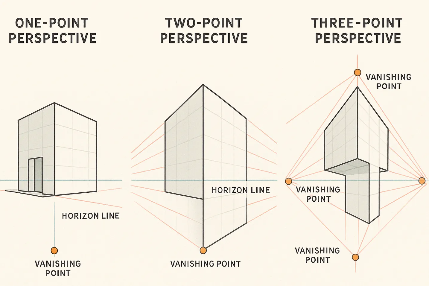
One-Point Perspective Applications
One-point perspective serves as the foundation for many architectural drawings. This perspective system works exceptionally well when viewing buildings straight-on or when looking down long architectural spaces like corridors or streets.
Characteristics and Construction
In one-point perspective, all lines perpendicular to the picture plane converge to a single vanishing point on the horizon line. Vertical lines remain truly vertical, and horizontal lines parallel to the picture plane stay horizontal. This creates a stable, easily understood view that emphasizes the frontal characteristics of architecture.
The grid method excels in one-point perspective because the grid squares on vertical surfaces maintain their square shape. Only the receding surfaces show perspective distortion, and these follow predictable patterns. Artists can use the grid to ensure equal spacing of elements like windows or columns as they recede toward the vanishing point.
Practical Applications
Street scenes looking directly down a road exemplify one-point perspective. The building facades on either side remain largely undistorted, while the street and sidewalks converge toward the vanishing point. The grid helps maintain consistent building heights and window alignments along the entire street length.
Interior architectural views often employ one-point perspective. A view down a hallway, into a room, or through a colonnade benefits from this approach. The grid ensures that floor tiles, ceiling coffers, and wall decorations maintain proper proportional relationships as they recede into the distance.
Frontal facade drawings represent another ideal application. When documenting historical buildings or creating elevation-style drawings with subtle depth, one-point perspective provides just enough spatial information without complicating the drawing process. The grid keeps ornamental details properly aligned across the facade.
Two-Point Perspective for Dynamic Architecture
Two-point perspective dominates architectural drawing because it captures how we typically view buildings—from an angle that reveals two sides. This perspective system creates dynamic, engaging views while maintaining the vertical integrity crucial for architectural subjects.
Setting Up Two-Point Perspective
Establishing accurate two-point perspective requires careful initial setup. The horizon line should reflect the actual eye level from which the building is viewed. Vanishing points must be placed far enough apart to avoid distortion—a common beginner's error that creates unnaturally dramatic convergence.
The grid method provides crucial support during setup. By establishing a grid on the ground plane first, artists can project vertical elements with confidence. Each grid intersection on the ground corresponds to a potential vertical element, creating a three-dimensional framework for the building.
Managing Convergence with Grids
The challenge in two-point perspective lies in maintaining consistent convergence angles throughout the drawing. Every horizontal line must aim toward one of the two vanishing points, and the rate of convergence must remain consistent. The grid acts as a verification system, ensuring that windows on upper floors align properly with those below.
For complex buildings, artists often create separate grid systems for each major plane. The front facade might have one grid following the left vanishing point, while the side facade follows the right vanishing point. These grids intersect at the building's corner, creating reference points for architectural details that wrap around corners.
Common Two-Point Scenarios
Building corners viewed at 45-degree angles represent the classic two-point perspective scenario. This view reveals equal amounts of two facades, creating balanced compositions. The grid helps maintain symmetry when the building itself is symmetrical, ensuring that details on both visible faces receive equal treatment.
Street corners with multiple buildings introduce additional complexity. Each building requires its own perspective construction, but all must share the same horizon line and vanishing points. The grid method helps manage this complexity by providing consistent reference points across all structures.
Architectural complexes with multiple connected buildings benefit enormously from grid-based two-point perspective. The grid ensures that connecting elements like walkways, shared rooflines, or aligned windows maintain proper relationships despite the perspective challenges.
Three-Point Perspective for Dramatic Views
Three-point perspective adds vertical convergence to the standard two-point system. This creates dramatic views essential for capturing the experience of looking up at tall buildings or down from elevated viewpoints.
When to Use Three-Point Perspective
Skyscraper drawings almost always require three-point perspective. When standing at street level looking up at tall buildings, vertical lines converge toward a vanishing point high above. The grid method helps control this convergence, preventing the building from appearing to lean backward excessively.
Aerial architectural views present the opposite scenario—vertical lines converge toward a point below. Whether drawing from drone photography or elevated viewpoints, three-point perspective captures the true experience of looking down at buildings. The grid provides crucial reference points for maintaining building proportions despite the dramatic viewing angle.
Managing Complexity
Three-point perspective introduces significant complexity. Every line in the drawing angles toward one of three vanishing points, and maintaining accuracy becomes challenging. The grid method proves invaluable here, providing a systematic way to verify angles and proportions.
Artists often work with a simplified grid in three-point perspective, focusing on major divisions rather than fine details. The dramatic viewing angles mean that fine architectural details may not be visible or may be too compressed to render effectively. The grid helps artists make intelligent decisions about what to include and what to simplify.
Perspective Grids for Complex Architecture
Some architectural subjects demand specialized perspective grid systems that go beyond basic one-, two-, or three-point approaches.
Cylindrical and Curved Buildings
Modern architecture increasingly features curved forms that challenge traditional perspective systems. Cylindrical towers, curved facades, and organic architectural forms require adapted grid approaches. Artists might use radial grids that follow the curve, or create a series of vertical grid lines that map the curved surface.
The key lies in understanding the underlying geometry. A cylindrical building still follows perspective rules—it's just that the "flat" grid must wrap around the curved form. By establishing key vertical lines and horizontal divisions, artists can create a framework for accurately drawing curved architecture.
Multi-Level Perspective Challenges
Buildings with multiple setbacks, terraces, or varying floor heights present unique challenges. Each level might require its own horizon line consideration, especially in tall buildings where the viewing angle changes significantly from bottom to top.
The grid method helps by establishing clear horizontal divisions at each level. Artists can then adjust the perspective slightly for each section while maintaining overall coherence. This approach proves particularly valuable for modern buildings with irregular profiles or historical buildings with multiple additions.
Capturing Architectural Details Through Grids
Architectural details bring buildings to life, transforming basic structures into characterful designs. The grid method excels at managing these details, providing a systematic approach to elements that might otherwise overwhelm. From repetitive window patterns to intricate ornamental carvings, grids ensure each detail maintains proper proportion and alignment within the overall composition.
Managing Repetitive Architectural Elements
Architecture thrives on repetition. Windows march across facades in regular rhythms, columns create consistent intervals, and decorative elements repeat in predictable patterns. This repetitive nature makes architecture particularly suited to grid-based drawing methods.
Window Systems and Fenestration
Windows represent the most common repetitive element in architectural drawing. A typical building facade might feature dozens of identical windows, each requiring accurate placement and proportion. The grid method transforms this potentially tedious task into a systematic process.
The approach begins with careful analysis of one complete window unit. Artists should map this first window thoroughly, noting its proportions within the grid squares. This includes the window frame, any divided lights, surrounding trim, and shadow patterns. Once this template is established, the grid facilitates accurate replication across the facade.
Perspective adds complexity to window repetition. As windows recede along a building face, they appear progressively smaller and closer together. The grid helps manage this diminishment consistently. By tracking how window width reduces across grid squares, artists maintain accurate perspective throughout the facade.
Different window types require adapted approaches. Arched windows need careful plotting of the curve within grid squares. Bay windows project from the facade, requiring additional perspective consideration. Dormer windows break the roofline, demanding integration with the building's overall form. The grid provides reference points for all these variations while maintaining consistency.
Column and Pillar Arrangements
Classical and neoclassical architecture features prominent column arrangements that demand precise spacing and proportion. The grid method proves invaluable for capturing these architectural elements accurately.
Columns follow strict proportional rules in classical architecture. The column diameter relates mathematically to its height, and the spacing between columns (intercolumniation) follows established ratios. The grid helps artists maintain these proportions even when drawing from photographs where lens distortion might obscure true relationships.
Entasis—the subtle swelling of classical columns—presents a particular challenge. This slight curve prevents columns from appearing concave. The grid allows artists to plot this curve accurately by noting where the column profile deviates from straight vertical lines within each grid square.
Column capitals and bases contain intricate details that benefit from grid subdivision. A Corinthian capital with its acanthus leaves and volutes might require a finer grid overlay to capture accurately. By subdividing the grid squares containing these elements, artists can maintain detail accuracy without overwhelming the overall drawing process.
Balconies, Cornices, and Projecting Elements
Projecting architectural elements create shadow patterns and perspective challenges that the grid method helps resolve. Balconies, cornices, window hoods, and other projections must maintain consistent relationships with the main building mass.
The key lies in understanding how these elements project from the primary building plane. The grid establishes the base plane, and artists can then measure projections in terms of grid units. A cornice might project one-quarter of a grid square, while a balcony extends a full square. This systematic approach ensures consistency across all projecting elements.
Shadow patterns from projecting elements follow predictable paths based on light direction. The grid helps plot these shadows accurately, creating the three-dimensional illusion essential for convincing architectural drawings. By noting where shadows fall within grid squares, artists maintain consistent light logic throughout the drawing.
Ornamental and Decorative Details
Architectural ornamentation ranges from simple moldings to elaborate carved facades. The grid method provides a framework for managing this complexity without losing sight of overall proportions.
Approaching Complex Ornamentation
Highly decorated buildings like Gothic cathedrals or Baroque palaces can overwhelm with their detail density. The grid method advocates a hierarchical approach: establish major forms first, then progressively add finer details.
Initial grid work should capture the overall shape and position of ornamental areas. A Gothic portal might occupy six grid squares in width and eight in height. Within this framework, artists can identify major subdivisions—the tympanum, archivolt layers, jamb figures, and door panels.
Progressive subdivision allows manageable detail development. Those initial six-by-eight grid squares can be subdivided into smaller units for detailed work. This approach prevents artists from becoming lost in details before establishing proper overall proportions.
Grid Strategies for Different Ornamental Styles
Different architectural styles require adapted grid approaches. Gothic tracery with its flowing lines benefits from plotting key intersection points where stone mullions meet. The grid provides these reference points while allowing the organic curves to flow naturally between them.
Classical ornament like egg-and-dart moldings or dentil courses involves precise repetition. The grid excels here, helping artists maintain consistent spacing and size for these repeating elements. By establishing the pattern within one or two grid squares, artists can extend it confidently across entire entablatures.
Art Nouveau and Art Deco buildings feature organic or geometric patterns that challenge traditional grid approaches. Here, the grid serves as an underlying structure while allowing decorative elements to flow across grid boundaries. The key is using the grid for proportion and alignment without letting it constrain the ornamental design's essential character.
Balancing Detail and Overall Impact
The grid method helps artists make intelligent decisions about detail inclusion. Not every carved element needs individual rendering; sometimes, suggesting texture and pattern proves more effective than literal reproduction.
By working systematically through grid squares, artists can maintain consistent detail levels across the drawing. This prevents the common problem of over-detailing certain areas while neglecting others. The grid acts as a pacing guide, helping artists distribute their effort effectively across the entire architectural subject.
Step-by-Step Architectural Drawing Process
A systematic approach to architectural drawing ensures consistent results and prevents common pitfalls. The grid method provides structure to this process, guiding artists from initial analysis through final details. This step-by-step methodology has proven effective across all architectural styles and complexity levels.
Phase 1: Initial Analysis and Planning
Before placing any lines on paper, thorough analysis of the architectural subject establishes a foundation for success. This planning phase, though sometimes overlooked by eager artists, determines the drawing's ultimate quality and accuracy.
Understanding the Building's Character
Every building tells a story through its architecture. A Gothic cathedral speaks of soaring spiritual aspiration, while a Bauhaus structure emphasizes functional clarity. Understanding this essential character guides artistic decisions throughout the drawing process.
Begin by identifying the building's architectural style and period. This knowledge informs expectations about proportions, decorative elements, and structural logic. A Renaissance palace follows different rules than a contemporary glass tower, and recognizing these differences prevents inappropriate artistic choices.
Study the building's primary forms and how they relate. Note the hierarchy of elements—which features dominate, which provide supporting roles, and which add decorative flourish. This analysis helps prioritize effort during the drawing process, ensuring that primary elements receive appropriate emphasis.
Selecting the Optimal Viewpoint
Viewpoint selection dramatically impacts an architectural drawing's success. The chosen angle should reveal the building's character while presenting manageable perspective challenges. Consider multiple options before committing to a particular view.
Straight-on elevations work well for documenting architectural details but may lack dynamism. Three-quarter views revealing two facades create more engaging compositions while introducing perspective complexity. The grid method accommodates any viewpoint, but some prove more practical than others for specific subjects.
Consider the building's intended viewing experience. Monumental structures designed to impress from below might benefit from a low viewpoint that emphasizes their scale. Intimate buildings meant for close engagement might require eye-level views that capture human-scale details.
Composition and Cropping Decisions
Architectural drawings need not include every visible element. Strategic cropping can strengthen compositions and focus attention on significant features. The grid method facilitates intelligent cropping by revealing natural division points.
Consider including enough context to ground the building without overwhelming the composition. A small amount of surrounding environment—adjacent buildings, landscaping, or street elements—helps viewers understand scale and setting. Too much context, however, dilutes focus on the primary architectural subject.
Plan for paper orientation early. Tall buildings naturally suit portrait orientation, while sprawling complexes benefit from landscape format. Some subjects might require creative solutions, such as diagonal compositions that maximize paper usage for oddly proportioned buildings.
Phase 2: Grid Construction and Transfer
With analysis complete, the practical work of grid construction begins. This phase establishes the framework that guides all subsequent drawing efforts.
Creating the Reference Grid
Modern artists often work from photographic references, making digital grid creation practical. Whether using specialized software or simple image editing tools, overlay a grid that balances detail needs with manageable complexity.
Consider the reference image's quality and size. High-resolution images support finer grids, while smaller references limit practical grid density. Ensure grid lines remain visible without overwhelming the architectural details they're meant to organize.
Save or print the gridded reference at a size that allows comfortable viewing while drawing. Many artists create multiple versions—an overall view with a basic grid and detail crops with finer grids for complex areas.
Scaling and Transferring the Grid
The transfer process requires careful attention to maintain proportional accuracy. Begin by determining the drawing size relative to the reference. This scaling factor applies to both the overall dimensions and the grid divisions.
Construct the drawing grid lightly with hard pencils (2H or H). These lines should be visible enough to guide work but light enough to erase or incorporate into the finished drawing. Use tools like T-squares and triangles to ensure grid accuracy—a warped grid guarantees a warped drawing.
For large drawings, consider creating the grid in sections. This approach prevents accumulated errors that might arise from extending measurements across large distances. Regular checks against the reference ensure the grid remains accurate throughout.
Establishing Perspective Framework
If the architectural subject involves perspective, establish vanishing points and horizon lines before proceeding. The grid helps verify perspective construction—receding lines should create a logical pattern within the grid framework.
For complex perspectives, create separate grids for major planes. A building corner in two-point perspective might have one grid for each visible face. These grids share common points at the building's corner, creating reference points for elements that wrap around the edge.
Phase 3: Progressive Drawing Development
With the grid framework established, the actual drawing process begins. The grid method encourages systematic development that builds complexity gradually.
Blocking Basic Forms
Initial drawing efforts should establish the building's major masses. Work lightly, using the grid to position primary elements accurately. This phase captures overall proportions and spatial relationships without concern for details.
Focus on large shapes that define the building's silhouette. The main building mass, major wings or additions, and significant projections like towers or porticoes deserve attention first. Each element should occupy the correct grid squares according to the reference.
Avoid the temptation to develop any area fully during this phase. The goal is establishing a proportionally accurate framework that supports subsequent detail work. Think of this phase as creating an architectural armature upon which details will hang.
Developing Primary Features
With basic forms established, add primary architectural features. Windows, doors, major divisions between floors, and significant structural elements like columns or buttresses enter the drawing at this stage.
Use the grid to ensure consistent spacing and sizing of repetitive elements. If windows occupy one grid square in width and two in height on the reference, maintain these proportions in the drawing. This consistency creates the rhythm essential to convincing architectural representation.
Work across the entire drawing rather than completing one area before moving to another. This approach maintains consistent development and prevents proportion drift that can occur when focusing too intensely on isolated areas.
Adding Architectural Details
Detail development represents the most time-intensive phase but also the most rewarding. The grid framework established earlier now pays dividends, providing reference points for accurate detail placement.
Approach details systematically, perhaps working through grid squares in a logical sequence. This methodical approach ensures no areas are overlooked and maintains consistent detail density throughout the drawing.
Balance literal representation with artistic interpretation. Not every brick needs individual rendering, nor does every decorative element require complete articulation. The grid helps gauge appropriate detail levels—if a decorative frieze occupies half a grid square, its general pattern and character matter more than exact reproduction of every element.
Refinement and Final Adjustments
The final phase involves stepping back to assess the drawing holistically. Check proportions against the grid, verify perspective consistency, and ensure architectural logic throughout.
This is the time for subtle adjustments that enhance the drawing's impact. Strengthening certain lines can emphasize structural elements. Adding selective detail to focal areas while simplifying peripheral regions creates visual hierarchy. The grid remains valuable for these decisions, helping maintain accuracy even during artistic enhancement.
Advanced Techniques for Architectural Accuracy
Beyond basic grid application, advanced techniques elevate architectural drawings from competent to exceptional. These methods address specific challenges inherent in architectural representation while maintaining the systematic approach that makes the grid method so effective.
Understanding Architectural Measuring Systems
Architecture follows mathematical principles that the grid method can leverage for enhanced accuracy. Understanding these systems allows artists to verify their observations and correct photographic distortions.
Classical Proportional Systems
Classical architecture adheres to strict proportional relationships derived from ancient Greek and Roman principles. The orders—Doric, Ionic, and Corinthian—each follow specific ratios that govern every element from overall height to minute details.
Column proportions provide a fundamental example. In the Doric order, column height typically equals 6-8 times the base diameter. The Ionic order extends this to 8-9 diameters, while Corinthian columns reach 9-10 diameters. The grid method helps verify these proportions in drawings, ensuring classical buildings maintain their mathematical harmony.
Entablatures—the horizontal elements above columns—follow equally precise rules. The architrave, frieze, and cornice maintain specific proportional relationships that vary by order. By allocating grid squares to match these proportions, artists ensure accurate representation even when working from photographs taken at angles that might distort these relationships.
Pediments present particular challenges with their triangular forms. Classical pediments typically maintain a pitch between 12.5 and 16 degrees, creating a height roughly one-fifth to one-quarter of the base width. The grid provides reference points for plotting these angles accurately, preventing the common error of too-steep or too-shallow pediment proportions.
Modern Modular Systems
Contemporary architecture often employs modular systems based on standardized components and mathematical grids. Understanding these systems helps artists recognize and reproduce the underlying logic of modern buildings.
Curtain wall systems exemplify modular design. These facades consist of repeated units—typically combining windows and spandrel panels—that create rhythmic patterns across building faces. The drawing grid can align with these modules, turning complex facades into manageable repeated units.
Floor-to-floor heights in modern buildings often follow consistent measurements, typically ranging from 12 to 14 feet in commercial buildings. This consistency means that once artists establish the proportion for one floor, they can reliably replicate it throughout the building. The grid method excels at maintaining these consistent vertical rhythms.
Structural grids underlying modern architecture often express themselves in facade design. Column lines and beam positions create a visible framework that organizes windows, panels, and other elements. By recognizing and aligning the drawing grid with these structural grids, artists work in harmony with the building's design logic.
Light, Shadow, and Atmospheric Effects
Architectural drawings gain dimension and believability through accurate light and shadow representation. The grid method provides a framework for plotting these effects systematically.
Systematic Shadow Construction
Shadows follow predictable geometric rules based on light source position. The grid method transforms shadow plotting from guesswork to systematic construction. By establishing the light angle, artists can project shadows consistently throughout the drawing.
Cast shadows from projecting elements create particularly important effects in architectural drawings. A cornice might cast a shadow band across the facade below, while deep-set windows create dark recesses that punctuate the building surface. The grid helps plot these shadows accurately by showing where shadow edges fall within each grid square.
Form shadows—the shadows on surfaces turned away from the light—require different treatment. These shadows gradate from dark to light as surfaces curve or angle relative to the light source. The grid assists in mapping these gradations, ensuring consistent light logic throughout the drawing.
Time of Day Considerations
Architectural appearance changes dramatically with lighting conditions. Morning light from the east creates different shadow patterns than afternoon light from the west. The grid method helps artists maintain consistency when working from multiple reference photos taken at different times.
Understanding solar angles for specific locations and times enhances accuracy. Buildings photographed at noon in summer show minimal shadows, while low winter sun creates dramatic shadow patterns. The grid provides a framework for adjusting these effects intelligently when the reference photography doesn't capture the desired lighting.
Atmospheric Perspective in Urban Settings
Buildings exist within atmospheric conditions that affect their appearance. Distant buildings appear lighter and less distinct than foreground structures. The grid method helps manage these atmospheric effects systematically.
In urban scenes with multiple buildings at varying distances, atmospheric perspective becomes crucial. Foreground buildings might show full contrast and detail, while background structures fade progressively. The grid helps artists gauge appropriate detail levels for each distance plane, preventing the common error of rendering distant buildings with foreground clarity.
Common Architectural Drawing Challenges and Solutions
Even experienced artists encounter specific challenges when drawing architecture. The grid method provides solutions to these common problems, but understanding the issues helps prevent them from arising.
Technical Precision Challenges
Maintaining Perfectly Straight Lines
Architecture demands straight lines—a fundamental requirement that challenges many artists. Freehand lines inevitably waver, undermining the structural integrity that architectural drawings require. The grid method provides reference points, but executing straight lines remains a technical skill.
The solution combines proper tools with confident technique. Using a straightedge for all architectural lines ensures geometric accuracy. However, mechanical line-drawing can appear lifeless. The key lies in maintaining slight pressure variations along the straightedge, creating subtle line weight changes that add life while preserving straightness.
Grid lines serve as verification tools. Any architectural line should maintain consistent relationships with grid lines along its length. If a building edge gradually diverges from parallel grid lines, it indicates unwanted curvature. Regular checks against the grid catch these errors before they become embedded in the drawing.
Achieving Perspective Consistency
Mixed perspective represents one of the most common architectural drawing errors. Artists might unconsciously shift between one-point and two-point perspective within a single drawing, or allow vanishing points to drift during extended drawing sessions.
The grid method helps maintain perspective discipline. Once vanishing points are established, every receding line must aim toward the appropriate point. The grid provides intermediate checkpoints—a line passing through several grid squares should maintain consistent angles relative to the grid throughout its length.
For complex buildings with multiple perspective systems, create a perspective diagram before beginning the actual drawing. This diagram maps all vanishing points and major perspective lines, serving as a master reference throughout the drawing process. The grid integrates with this diagram, providing a coordinate system for maintaining perspective accuracy.
Perspective drift represents a common challenge in extended drawing sessions. During one cathedral interior drawing, after four hours of work, the left colonnade appeared to bend upward unnaturally. Investigation revealed the vanishing point had migrated two inches during the session. The solution involves marking vanishing points on tape beyond the paper edges—physical markers that cannot drift. The grid then builds from these fixed anchors, maintaining consistency throughout the drawing process.
Compositional Challenges
Balancing Detail Distribution
Architectural drawings often suffer from uneven detail distribution. Artists might lavish attention on an interesting doorway while merely suggesting adjacent walls, creating visual imbalance. The grid method helps distribute effort more evenly across the drawing.
Working systematically through grid squares prevents detail clustering. Rather than fully developing one area before moving to another, artists should build detail levels consistently across the entire drawing. This approach ensures that viewer attention flows naturally through the composition rather than getting stuck in over-detailed areas.
The grid also helps identify appropriate detail levels for different areas. Focal points might merit fine grid subdivision and extensive detail, while supporting areas work well with larger grid squares and suggested details. This hierarchical approach creates visual interest while maintaining overall balance.
Managing Scale Relationships
Buildings exist in relation to human scale, and drawings must reflect these relationships accurately. A doorway that appears too small or windows positioned too high destroy the believability of architectural drawings. The grid method provides a framework for maintaining proper scale relationships.
Including scale references helps verify proportions. A human figure, even roughly indicated, immediately reveals scale problems. Standard architectural elements provide additional references—doors typically measure 6'8" to 7' tall, residential windows often start 2'6" to 3' above floor level, and story heights generally range from 9' to 14'.
The grid facilitates scale consistency by establishing modular relationships. If one grid square represents three feet at human height level, this relationship guides proportions throughout the drawing. Regular reference to these established scales prevents gradual drift toward incorrect proportions.
Scale relationships prove crucial in architectural drawing. One Victorian townhouse study revealed this dramatically—the ornate bay windows appeared perfect in isolation, but adding a door for scale exposed a critical error: the windows were sized for giants. The solution involves establishing the first grid square to represent a standard door height (7 feet), providing an instant reality check for every other element. This single reference point prevents hours of effort on beautifully rendered but incorrectly scaled details. For creating accurate reference grids quickly, use our free grid drawing tool.
Environmental Integration Challenges
Contextualizing Buildings
Buildings rarely exist in isolation, yet many architectural drawings present them as objects floating in space. Integrating buildings with their environment—whether urban context or natural landscape—challenges artists to balance architectural focus with environmental integration.
The grid method extends beyond the building itself to organize environmental elements. Street levels, adjacent buildings, and landscape features can align with the grid system, creating unified compositions. This integration prevents the building from appearing pasted onto a separate background.
Consider atmospheric effects when placing buildings in context. Urban environments often include atmospheric haze, particularly for distant buildings. The grid helps gauge appropriate detail levels—distant buildings might occupy grid squares but receive minimal detail development, suggesting their form without competing with the primary subject.
Handling Reflective Surfaces
Modern architecture increasingly features glass facades that reflect surrounding environments. These reflections add complexity that the grid method helps organize. Rather than random reflection patterns, the grid provides a framework for plotting what appears in reflective surfaces.
Reflections follow the same perspective rules as the building itself. The grid that organizes the building also organizes its reflections, ensuring consistency. Sky reflections, adjacent buildings, and ground plane reflections each occupy predictable areas within the grid framework.
The key lies in understanding that reflections create a secondary image plane. While the building surface follows one grid system, the reflected image might require its own perspective construction. The grid method accommodates this complexity by allowing multiple organizational systems within a single drawing.
Different Architectural Styles and Grid Applications
Each architectural style presents unique challenges and opportunities for grid-based drawing. Understanding how different styles relate to grid systems helps artists choose appropriate approaches for specific subjects.
Classical Architecture
Classical architecture embodies mathematical precision and harmonious proportions, making it ideally suited to grid-based drawing methods. The style's emphasis on symmetry, repetition, and modular design aligns perfectly with grid principles.
Greek and Roman architecture follows strict mathematical relationships. The golden ratio appears throughout classical design, from overall facade proportions to individual element sizing. The grid method helps artists recognize and reproduce these relationships, ensuring drawings capture the mathematical harmony that defines classical architecture.
Symmetry dominates classical design, with central axes organizing entire facades. Aligning grid systems with these axes simplifies the drawing process dramatically. Elements on one side mirror those on the other, allowing artists to develop half the facade in detail, then replicate it with grid-guided accuracy.
The repetitive nature of classical elements—columns, metopes, triglyphs, and modillions—suits grid-based reproduction perfectly. Once artists establish the proportion and detail of one element, the grid facilitates accurate replication across the entire structure. This systematic approach captures classical architecture's rhythmic beauty.
Gothic Architecture
Gothic architecture challenges grid methods with its vertical emphasis, pointed arches, and intricate ornamental details. However, beneath the apparent complexity lies geometric order that grids can capture effectively. For tackling such intricate subjects, how the grid method can help you break down complex drawings offers valuable strategies.
The pointed arch, Gothic architecture's defining element, follows precise geometric construction. By plotting key points—the spring points and apex—within the grid, artists can construct accurate Gothic arches. The grid helps maintain consistency when drawing multiple arches, ensuring they share the same proportions and character.
Tracery patterns in Gothic windows appear impossibly complex but often derive from simple geometric principles. Rose windows, for instance, typically feature radial symmetry that grid subdivision can organize. By identifying the underlying geometric structure, artists can use grids to manage even the most intricate tracery patterns.
The vertical emphasis of Gothic architecture requires adapted grid approaches. Vertical grid divisions might be finer than horizontal ones, reflecting the style's upward thrust. This asymmetric grid better captures Gothic proportions while maintaining systematic organization.
Modern Architecture
Modern architecture's clean lines, minimal ornamentation, and visible structural systems align naturally with grid methods. Many modern buildings literally express grid systems in their design, making grid-based drawing particularly appropriate.
The International Style's emphasis on horizontal and vertical elements creates compositions that grids organize effortlessly. Ribbon windows, pilotis, and flat roofs follow geometric principles that translate directly to grid systems. The absence of ornament means artists can focus on proportions and relationships—exactly what grids facilitate best.
Curtain wall systems in modern high-rises exemplify grid-based design. These facades consist of modular units repeated across the building surface. By aligning the drawing grid with these modules, artists work in harmony with the architecture's inherent organization. This approach turns potentially monotonous facades into systematic drawing exercises.
Contemporary parametric architecture introduces new challenges with its curved and flowing forms. However, even these complex shapes often derive from mathematical principles that grids can help organize. By understanding the underlying geometry, artists can adapt grid systems to capture even the most avant-garde architectural forms.
Vernacular Architecture
Vernacular architecture's informal, organic qualities might seem incompatible with rigid grid systems. However, grids provide valuable structure while allowing the charm and character of vernacular buildings to emerge.
The irregular forms of vernacular architecture—sagging rooflines, non-perpendicular walls, organic materials—require flexible grid application. Rather than forcing these buildings into rigid geometric frameworks, artists can use grids as general guides while allowing natural irregularities to express themselves.
Texture plays a crucial role in vernacular architecture. Thatched roofs, rough stone walls, and weathered timber create surface interest that strict grid adherence might destroy. The grid provides overall proportional guidance while allowing textural freedom within individual grid squares.
The key to drawing vernacular architecture lies in balancing accuracy with character. The grid ensures major proportions remain correct—the relationship between roof and walls, the positioning of doors and windows—while permitting the irregularities that give vernacular buildings their appeal.
Handling Mid-Drawing Grid Adjustments
Even experienced artists occasionally discover grid alignment issues partway through a drawing. Rather than starting over, professional techniques allow for intelligent adjustments that salvage hours of work while correcting fundamental problems.
Recognizing Grid Drift Early
Grid drift occurs when cumulative small errors create noticeable misalignment. The earlier you catch these issues, the easier they are to correct. Regular checks at natural breaking points—completing a floor level, finishing a major architectural element—help identify problems before they compound.
Compare diagonal measurements across your grid. If a building appears square in the reference, diagonal grid counts should match. When diagonals differ by more than half a grid unit, alignment issues need addressing. This simple check saved me from numerous failed drawings once it became routine.
Strategic Grid Subdivision
When discovering that initial grid density proves insufficient for certain areas, strategic subdivision offers a solution. Rather than reconstructing the entire grid, subdivide only the squares containing complex details. This localized refinement maintains overall proportions while providing necessary detail guidance.
The key lies in systematic subdivision. Dividing each square into quarters (2x2) or ninths (3x3) maintains mathematical relationships. Mark these subdivisions lightly—they guide detail work without overwhelming the primary grid structure. This technique proves invaluable when unexpected ornamental complexity emerges in architectural references.
Compensating for Reference Distortions
Photographic references often contain lens distortions that become apparent only during drawing. Wide-angle lens barrel distortion makes straight architectural lines curve. Rather than faithfully reproducing these distortions, the grid helps identify and correct them.
When vertical building edges bow outward in photos, use the grid to plot where these lines should fall if truly vertical. Trust architectural logic over photographic artifacts. Buildings have straight edges—if the photo suggests otherwise, the lens, not the building, created that curve. The grid provides the framework for these intelligent corrections.
Professional Techniques for Architectural Excellence
Mastering architectural drawing requires combining systematic approaches with artistic sensitivity. These professional techniques, developed through years of practice, help artists achieve exceptional results.
Establishing Visual Hierarchy
Not all architectural elements deserve equal attention. Professional architectural drawings guide viewers through visual hierarchy, emphasizing significant features while subordinating supporting elements. The grid method facilitates this hierarchy through selective detail development.
Primary focal points—often entrances, significant windows, or distinctive architectural features—merit the finest grid subdivision and most careful detail development. Secondary elements receive moderate treatment, while background areas might only suggest architectural forms. This hierarchical approach creates drawings that communicate effectively rather than overwhelming with uniform detail.
Line weight variation enhances visual hierarchy. Primary architectural elements receive bold, confident lines, while secondary elements use medium weights. Fine details and texture suggestions employ the lightest lines. The grid helps organize these line weight decisions systematically across the drawing.
Managing Complex Compositions
Architectural subjects often include multiple buildings, varying perspectives, and environmental context. Professional artists use grid systems to organize these complex compositions while maintaining unity.
Establishing a master grid that encompasses the entire composition provides overall organization. Within this master grid, individual buildings might have their own grid systems reflecting their specific perspective requirements. This nested approach maintains both local accuracy and global coherence.
Foreground, middle ground, and background require different treatments. The grid helps artists gauge appropriate detail levels for each spatial zone. Foreground architecture might use fine grid divisions supporting extensive detail, while background buildings occupy larger grid areas with suggested forms.
Time-Efficient Working Methods
Professional architectural drawing often involves deadlines and efficiency requirements. The grid method, properly applied, actually saves time by preventing errors and organizing workflow. For exploring different artistic approaches to architectural subjects, using grid drawing to improve your charcoal drawings demonstrates how various mediums can enhance architectural representation.
Initial time investment in accurate grid construction pays dividends throughout the drawing process. A well-constructed grid eliminates guesswork, reduces errors, and provides constant verification. This upfront investment prevents time-consuming corrections later.
Working in passes across the entire drawing proves more efficient than completing areas sequentially. First passes establish major forms, second passes add primary details, and subsequent passes develop increasing refinement. This approach, guided by the grid system, ensures consistent development and prevents overworking individual areas.
Professional efficiency requires systematic working methods. A three-pass system prevents wasted effort on drawings with fundamental errors. Pass one establishes major shapes in 20 minutes using the grid. Pass two adds primary features in 40 minutes. Pass three develops selective details where they matter most. This systematic approach prevents spending hours on details only to discover proportion errors. The grid enforces this discipline—progress occurs only when each pass verifies correctly against grid references. This methodical approach applies equally to still life compositions and architectural subjects.
Quick Grid Solutions for Common Architectural Elements
Through years of architectural drawing, certain elements repeatedly challenge artists. These quick solutions address the most common pain points with practical grid-based approaches.
Circular Windows and Arches
Circular elements within rectangular grid systems need strategic plotting. Mark the circle's center point at a grid intersection. Plot four points where the circle crosses grid lines (top, bottom, left, right). Add four more points at 45-degree angles where the circle intersects diagonal grid lines. These eight points provide sufficient guidance for smooth curves. For elliptical arches, use the same technique but adjust for the compressed vertical or horizontal dimension.
Repeating Decorative Patterns
Ornamental friezes and decorative bands often feature repeating motifs. Count the pattern repetitions within a measured grid section. If five complete motifs fit within three grid squares, you've established the rhythm. Mark these intervals lightly along the entire decorative band before drawing any details. This preliminary rhythm mapping prevents compression or expansion errors common when drawing patterns intuitively.
Roof Angles and Dormers
Rooflines challenge grid alignment because they rarely align with horizontal or vertical grid lines. Plot the roof peak and eave points first using grid coordinates. The angle between these points remains consistent for the entire roof plane. For dormers, establish their base alignment with the main roof, then use smaller grid subdivisions to capture their proportions. Each dormer follows the same angle logic as the main roof.
Modern Glass Reflections
Contemporary buildings with glass facades require a dual approach. First, use the grid to establish the building's actual structure—the window frames and solid elements. Then, treating reflections as a semi-transparent overlay, map what appears in the glass using the same grid. The grid coordinates help maintain logical reflection angles. Sky reflections in upper windows, street-level activity in lower panes—the grid organizes these complex overlapping images.
Common Questions About Architectural Grid Drawing
Expand your workflow with large-scale grid strategies, tighten depth control via the grid perspective guide, and refine advanced processes in Mastering the Grid Technique in Drawing and Painting.
Ready to Try the Grid Method?
Put these techniques into practice with our free grid generator tool—trusted by 170,000+ artists worldwide.
Create Your Grid Now →