
Buildings go wrong because small errors compound: a vertical off by two degrees, window spacing off by a millimetre per bay, and by the far end of the facade the building leans. A grid over the reference gives you fixed checkpoints — where each corner lands, where each edge crosses a line — so an error stays inside one cell instead of propagating across the drawing.
You can put a grid on your own reference with the grid maker online. Everything below assumes a photograph, a pencil and a flat sheet of paper. The perspective construction itself, drawn from scratch without a photo, is covered in understanding perspective with grid drawing.
Grid both, block in, then subdivide
- Pick a friendly reference. Square-on gives you the easiest drawing and the flattest one; a three-quarter view showing two faces is more interesting and costs you a second vanishing point, so decide which trade you want before you grid anything. Then check the photo: horizon visible, no strong lens bend. Look at the vertical edges of the building in your photo. If they bow outward near the frame edge, the lens curved them. Pick another shot, or crop to the middle two-thirds.
- Put the same grid on both: if the reference is 8 columns x 10 rows, the paper is 8 columns x 10 rows. The cells change size; the counts never do. Cell A1 on the photo is cell A1 on the paper.
- Match the grid to the photo's shape. A wide facade wants more columns than rows — 12x8, not 8x10 — or your cells stop being square and every horizontal measurement is off.
- Block in the big shapes. Blocking in means laying down the outline and the main planes as light straight lines with no detail in them: the silhouette, the ground line, the corner where two faces meet, and the major horizontal breaks between floors and at the roof.
- Place your anchors. Mark the corners of doors and windows, and every point where a building edge crosses a grid line. These are the numbers you will check everything else against.
- Build the repetition. Place the first and last window in a row from the grid, then subdivide between them with diagonals rather than by eye.
- Shade in three values if you want tone: light plane, shadow plane, and the deep holes where the windows are.
What you need: a reference photo, a pencil you can erase (HB or H), an eraser, and a printed or on-screen grid over the photo. A ruler helps. Nothing else. If you want to compare pencils and paper properly, see drawing materials.
How dense should the grid be?
| Building | Grid | Why that number |
|---|---|---|
| Flat modern facade, few openings | 8x10 | One window lands inside roughly one cell |
| House or shopfront with trim and cornices | 12x16 | A window plus its surround fits one cell |
| Church, civic building, heavy ornament | 16x20 | The smallest thing you intend to draw fits one cell |
The rule underneath all three: pick the density so that the smallest element you actually intend to draw fits inside about one cell. Finer than that and you are colouring in squares. Coarser and you are guessing inside them.
One part of a building is often far busier than the rest, and a cathedral portal does not justify a 20x25 grid across the sky. Subdivide only the cells that need it, halving or quartering them so every fine line sits on a coarse one. Breaking down complex drawings goes through where to spend that extra density.
Placing a row of windows in perspective
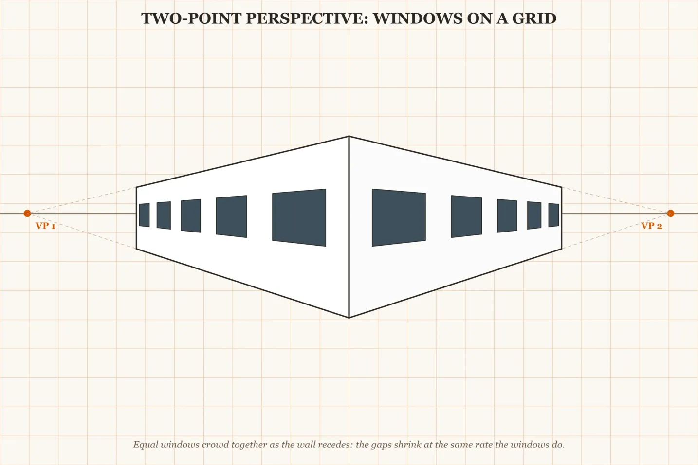
Equal windows on a receding wall are not equally spaced on your paper. They crowd together toward the vanishing point. Halving by eye puts the middle window too far from the near end every time.
Do this instead. Draw the near window and the far window from the grid: those two you can read off the reference directly. Then draw the two diagonals of the rectangle they bound. Where the diagonals cross is the perspective centre of the wall. Draw a vertical there and you have the middle window, correctly foreshortened. Repeat inside each half for four bays, again for eight.
The check: the gaps between windows must get narrower toward the vanishing point, and each window must get narrower by the same proportion. If gap 3 is wider than gap 1 while the windows are getting smaller, the construction is wrong. Windows that get narrower while the gaps between them get wider is not a hard drawing to fix, it is a geometrically impossible building.
If it went wrong: you halved by eye. Erase back to the two end windows and use the diagonals.
Two extensions of the same construction earn their keep. To carry a row further than the reference shows, take two verticals you trust, find the perspective midpoint of the far one with its bay diagonals, then draw a line from the top of the near vertical through that midpoint. Where it meets the base line is the next vertical, at the correct diminishing interval, and you can repeat that as far as the wall runs. The second extension is vertical: floor levels on a receding wall crowd together exactly as the windows do, so the diagonals of a two-storey rectangle give you the floor line between them.
The grid places things, perspective decides where they belong
Alberti described the device in 1435: a gridded veil between the eye and the subject, a matching grid on the paper, one fixed eye position. Dürer's 1525 woodcuts show the same thing built out of wood. It is the direct ancestor of what you are about to do — and it is worth being precise about what it did. The veil copied a view; it did not construct one. Perspective was built separately, with rulers and vanishing points. That division still holds: the grid places things, perspective decides where they belong.
In practice that means the grid will tell you a roof edge crosses the third vertical two cells down, and it will not tell you whether that edge is aimed at the right vanishing point. You need both.
Where the two vanishing points go
Put the two vanishing points at least twice your drawing's width apart, which means both of them land off the paper. Tape strips out to either side and mark them there. Closer than that and the building looks like it is bulging toward you.
Marking them physically also stops them drifting. Over a long session an unmarked vanishing point migrates, and a colonnade that started straight begins to bend. A pencil mark on tape cannot move.
The horizon line is your eye level in the photograph, nothing else. Find it by looking for the horizontals that do not converge: those are the ones at your eye height, and they sit on the horizon.
Setbacks and terraces do not get their own rules
A drawing has exactly one horizon line, fixed by your eye level. Buildings with setbacks, terraces or varying floor heights do not change that.
The grid handles this by marking each setback as its own horizontal division. Every one of those lines still runs to the same two vanishing points on the same horizon — a terrace nine floors up converges harder than the entrance, because it is further above eye level, not because it has its own rules.
When three-point perspective is worth it
Three-point perspective is for when you want the reader to feel the height: standing at the base looking up, or looking down from a drone. It is not the default for tall buildings. Architectural renderers usually keep verticals vertical on purpose, which is two-point, because a leaning tower reads as a mistake in a presentation drawing.
If you do use it, keep the grid coarse. At those angles the fine detail is compressed to the point where it cannot be drawn anyway, and a dense grid only gives you more places to make a small error.
Classical buildings come with their own arithmetic
Classical facades are governed by simple whole-number ratios of module and column diameter, not, despite the persistent myth, by the golden ratio. The useful consequence: once you have measured one element in cells, the rest of the building is predictable, and a measurement that disagrees with the ratio is usually your measurement.
Column proportions
Greek Doric columns run roughly 4 to 6.5 base diameters in height, and the Parthenon sits near 5.5. The later Roman and Renaissance canon stretches Doric to about 8 diameters, Ionic to 9 and Corinthian to 10. Measure the base diameter of one column in grid cells, multiply, and you have the height it should reach. Photographs taken from below foreshorten columns badly, so this check catches errors your eye will accept.
Entasis: a real swelling, a false explanation
Classical columns swell slightly at mid-shaft — entasis. You will read everywhere that this corrects an optical illusion that makes straight columns look pinched. No experiment has ever produced that illusion, including tests on three-dimensional temple reconstructions, and current work points instead at buckling resistance and at the taper of the wooden columns the stone ones copied. What matters for drawing: the swelling is real and it is small. Plot the shaft as a straight line from the grid, then push the mid-height edges out by a fraction of a cell. If your reader can see the curve, you have overdone it.
Pediments and the band below them
The entablature is the horizontal band sitting on the columns, read from the bottom up as architrave, frieze and cornice. Its total depth is a fixed fraction of the column height in each order, so allocate whole cells to it before drawing any of its mouldings.
The pediment is the triangular gable above it, and its pitch is where most drawings go wrong. Greek temple pediments sit around 12.5 to 16 degrees, which puts the apex somewhere between one-ninth and one-seventh of the base width above the cornice. Roman and Renaissance ones are steeper — Vignola's rule gives about 22.5 — so check which tradition your building belongs to before you plot the angle. Either way, plot the apex as a grid coordinate and draw two straight lines to it. Angles drawn freehand come out too steep.
Four details that catch people out
Circular windows and arches
Mark the circle's centre at a grid intersection. Plot the four points where the circle crosses the grid lines running through that centre: top, bottom, left and right. Then draw the two diagonals of the four cells meeting at the centre. Where the circle crosses them gives four more points, at about 0.7 of the radius out in both x and y. Eight points carry a smooth curve. For an elliptical arch, the same construction works once you compress one axis.
Repeating decorative bands
On a face square to you, count the pattern repetitions against the grid. If five complete motifs fit in three cells, you have the rhythm: mark those intervals along the whole band before drawing a single detail. On a receding face the intervals are not equal, and you are back to the diagonal method from the window section.
Roof angles and dormers
Rooflines rarely align with anything on the grid. Plot the ridge and the eave points as coordinates first, then draw between them. The angle you get is the angle for the whole roof plane, so every dormer face parallel to it repeats that same angle. Only the dormer sizes change with distance.
Cornices, balconies and other projections
Anything that sticks out of the facade should be measured in cells, not guessed. A cornice might project a quarter of a cell where a balcony projects a full one, and keeping those figures consistent is what stops the facade from looking soft. Their shadows follow the same discipline: note where the shadow edge crosses each grid line, and the light stays logical across the whole building.
Catching the error before it compounds
The diagonal check
Check the diagonals. If the building reads as square in the reference, the two diagonal cell counts across it should match. More than half a cell apart means the grid, not the drawing, is off — fix it now, because every measurement after this inherits it.
Does it read at human scale?
Standard dimensions give you a reality check that pure proportion cannot. A door runs 6'8" to 7' (2.03 to 2.13 m) tall. Residential window sills sit 2'6" to 3' (0.76 to 0.9 m) above the floor. Story heights run 9' to 14' (2.7 to 4.3 m), with commercial floor-to-floor usually 12' to 14' (3.7 to 4.3 m).
Convert one of these into cells early: work out how many cells tall a 6'8" (2.03 m) door is in your drawing, and every window, balcony and cornice afterwards has something to be wrong against. Sketching a rough human figure at the entrance does the same job in ten seconds.
Subdividing without rebuilding the grid
When a patch turns out to need more reference points than you gave it, subdivide only that patch. Quarters (2x2) or ninths (3x3) keep the mathematics intact and every new line lands on an existing one. Mark the subdivisions lighter than the main grid so the two do not compete.
Trust the building, not the photograph
Photographs lie about straight lines. Wide-angle barrel distortion bends verticals, and perspective correction in editing software leaves its own artefacts. Buildings have straight edges. Where the photo disagrees, use the grid to plot where the line should fall if it were truly vertical, and draw that instead.
Straight lines and drifting angles
Use a straightedge for architectural lines and vary the pressure along it, so the line stays geometrically straight without going dead. Then check each long line against the grid it passes through. A building edge that slowly diverges from the grid lines around it is curving, and the earlier you catch that, the less of the drawing inherits it. The same applies to charcoal and other soft media, where grid drawing for charcoal covers how to keep edges crisp.
Common Questions About Architectural Grid Drawing
For work at wall size, large-scale grid strategies covers the scaling problems that only appear past a certain size, and the basics of grid drawing for beginners is the short version of the method itself.
Next: pick a photo of one building from your street, taken square-on, and grid it 8x10. Draw only the silhouette and the floor lines. When those hold, add the windows using the diagonal method above.
Ready to Try the Grid Method?
Put these techniques into practice with our free grid generator tool—trusted by 170,000+ artists worldwide.
Create Your Grid Now →